











Industry knowledge
Signal Integrity Challenges Specific to Encoder Cables in High-Speed Motion Control Systems
Encoder cables carry position and velocity feedback signals between rotary or linear encoders and motion controllers or servo drives. Unlike general-purpose control cables, they operate in an environment defined by two simultaneous and conflicting demands: the signal lines must transmit high-frequency digital pulses or fine analog waveforms with minimal distortion, while the cable runs alongside or is bundled with power cables supplying the very motors that generate substantial electromagnetic interference. The result is that encoder cable performance is determined not just by its own electrical parameters but by how those parameters interact with the specific encoder interface protocol and the noise environment of the installation.
Incremental encoders using TTL or differential RS-422 line driver outputs generate pulse trains at frequencies that scale directly with motor speed and encoder resolution. A 2,500-line-per-revolution encoder on a servo motor running at 3,000 RPM produces output pulses at 125 kHz per channel — and with quadrature decoding, the controller processes edge transitions at 500 kHz. At these frequencies, cable capacitance becomes a limiting factor: the distributed capacitance between signal conductors and between signal and shield slows the rise time of each pulse edge, reducing the maximum cable length over which the encoder can operate reliably. For RS-422 differential signals, a cable with a conductor-to-conductor capacitance of 100 pF/m will limit usable run length to well under 30 meters at 500 kHz edge rates, while a cable engineered for 50 pF/m or below can extend that range significantly.
Absolute encoder protocols — including EnDat, SSI, BiSS, and HIPERFACE — place additional demands on cable construction because they involve bidirectional communication between the encoder and drive at clock frequencies typically ranging from 1 MHz to 16 MHz. At these frequencies, characteristic impedance matching between the cable and the driver/receiver circuitry becomes significant. Impedance mismatches cause signal reflections that appear as noise on the data line, potentially corrupting position data. Properly constructed encoder cables specify a characteristic impedance of 100–120 Ω for differential pairs, maintained consistently along the full cable length, to minimize reflection-induced errors in high-resolution absolute feedback systems. Anhui Zhishang Cable Technology Co., Ltd. produces encoder cables with tightly controlled twist pitch and insulation geometry to achieve stable impedance values that support these demanding protocols.
Shielding Architecture: Why a Single Overall Shield Is Often Insufficient for Encoder Cables
The standard assumption that a single overall shield is adequate for signal cable shielding breaks down specifically in encoder cable applications, where multiple signal types with different noise susceptibilities share the same cable body. A typical encoder cable carries A/B/Z quadrature signal pairs, supply voltage and ground conductors for the encoder electronics, and sometimes a battery backup pair for absolute position retention — each with a different impedance, current level, and sensitivity to interference. When all of these are covered by a single overall shield only, inductive and capacitive coupling between the power supply conductors and the signal pairs within the cable remains uncontrolled, and the shield provides no protection against this internal crosstalk.
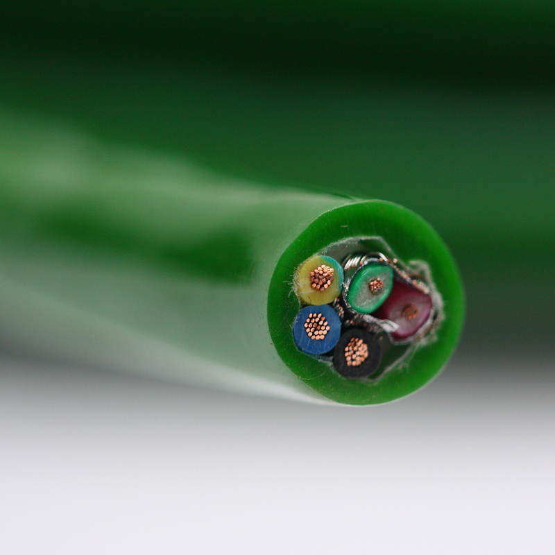
The solution used in high-performance encoder cables is a layered shielding architecture: individual pair shields for each differential signal pair, combined with an overall shield for the entire cable. The individual pair shields, typically aluminum-polyester foil with a drain wire, suppress capacitive coupling between adjacent signal pairs and between the signal pairs and the power conductors. The overall shield, either foil or tinned copper braid, provides the primary barrier against external electromagnetic interference from the motor drive, cable tray neighbors, and the general industrial EMI environment. This two-level approach adds to cable diameter and cost, but in precision motion control applications operating at sub-micron positioning resolution, the alternative — position feedback errors caused by noise — is far more expensive than the cable upgrade.
Shield grounding practice is as critical as shield construction. The overall shield of an encoder cable should be connected to protective earth at the drive/controller end only, forming a single-ended ground that prevents shield current loops driven by ground potential differences between the motor end and the control cabinet. If the shield is grounded at both ends and a ground loop exists — which is common in large machines where different structural steel sections are at slightly different potentials — the resulting shield current flows through the drain wire and induces a voltage on the signal lines it was meant to protect. Many intermittent encoder fault conditions in operational machinery trace back to this specific grounding error rather than to any fault in the cable or encoder itself.
| Shielding Configuration | External EMI Protection | Inter-Pair Crosstalk Suppression | Typical Application |
|---|---|---|---|
| Overall foil only | Moderate (HF) | None | Low-resolution incremental encoder, short runs |
| Overall braid only | Good (LF + HF) | None | General servo feedback, moderate noise environments |
| Individual pair foil + overall foil | Good (HF) | High | Multi-protocol absolute encoders, long runs |
| Individual pair foil + overall braid | Excellent (LF + HF) | High | High-resolution servo, heavy EMI environments |
Flex Life Requirements and Construction Differences Between Fixed and Moving Encoder Cable Installations
Encoder cables are installed in two fundamentally different mechanical environments that require distinct cable constructions: fixed routing from a stationary encoder on a machine frame to a control cabinet, and dynamic routing on moving machine axes such as CNC machining centers, robotic arms, linear actuators, and gantry systems. Treating these two installation types as interchangeable — using a fixed-installation cable in a dynamic application or over-engineering a drag-chain cable for a static route — leads to either premature mechanical failure or unnecessary cost.
For drag-chain and continuous-flex applications, encoder cable construction must address several simultaneous mechanical demands. The conductor stranding must be Class 5 or Class 6 per IEC 60228, using fine individual wires to distribute bending stress and maximize fatigue life — a Class 6 stranded conductor of 0.14 mm² cross-section may consist of 50 or more individual wires each below 0.06 mm in diameter. The insulation polymer must remain flexible across the full operating temperature range without stress cracking, ruling out general-purpose PVC in favor of TPE or specially compounded PVC with maintained low-temperature flexibility. The individual shields and overall shield must be constructed from fine-wire braid or lapped foil with sufficient overlap to maintain electrical continuity through millions of flex cycles without developing breaks or intermittent open-circuit conditions in the drain wire. Zhishang Cable designs its continuous-flex encoder cables with an optimized lay length for each stranded conductor element, ensuring that the helical geometry of the conductors and shields naturally accommodates the cable's bending without generating tensile overload in the outer elements.
The minimum bend radius specification for a drag-chain encoder cable is not a single static value — it differs between the dynamic bend radius (applied continuously during operation) and the installation bend radius (a one-time bend during routing). Dynamic bend radius for high-flex encoder cables is typically specified as 7.5× to 10× the cable outer diameter, while installation bend radius may be 5× or less. Applying the installation bend radius as a permanent bend — for example, routing the cable around a tight corner in a cable duct — creates a region of sustained mechanical stress that accelerates fatigue failure at that point even though the cable itself is not moving. This distinction must be clearly communicated to installation technicians, particularly in retrofit projects where new cables replace existing ones in already-established routing paths.
Power Supply Conductor Sizing Within Encoder Cables: Voltage Drop and Noise Coupling Trade-Offs
Most encoder cables include dedicated conductors for supplying operating voltage to the encoder electronics — typically 5V DC for TTL-output incremental encoders or 8–30V DC for HTL and many absolute encoder types. These power conductors are small in cross-section relative to their equivalents in power cables, but their sizing has a direct effect on encoder performance that is frequently overlooked. Voltage drop along the power supply conductors reduces the supply voltage at the encoder terminals, and encoders operating near the lower end of their specified voltage range may produce output signals with reduced amplitude, increased rise times, or — in the case of 5V TTL encoders with very tight voltage margins — intermittent logic level errors that are difficult to distinguish from noise-induced faults.
Calculating acceptable voltage drop requires knowing the encoder's current consumption, the cable run length, and the conductor cross-section. A 5V encoder drawing 150 mA over a 20-meter cable with 0.14 mm² supply conductors experiences approximately 0.86V of combined supply-and-return drop — more than 17% of the nominal supply voltage, which places the encoder well below its rated 5V supply and within the margin where output signal quality degrades. Increasing the supply conductor cross-section to 0.25 mm² reduces this drop to approximately 0.48V, restoring adequate supply margin. For installations where long cable runs are unavoidable, some servo drive manufacturers offer adjustable encoder supply voltage output that compensates for cable resistance, but this requires accurate knowledge of the cable's conductor resistance and cannot substitute for correct conductor sizing at the design stage.
Beyond voltage drop, the power supply conductors within an encoder cable are a potential noise injection path. Switching noise on the encoder supply — generated by the drive's internal power supply or conducted from the machine's DC bus — couples capacitively into adjacent signal pairs if the supply conductors are not adequately separated or shielded from the signal pairs within the cable. This is one reason why the power conductors in a well-designed encoder cable are often given their own individual shield or positioned at the cable periphery away from the signal pairs, rather than being distributed randomly within the cable bundle. As part of its application engineering support, Anhui Zhishang Cable Technology Co., Ltd. advises customers on power conductor cross-section selection and cable construction options based on actual encoder current requirements and installation distances, preventing supply-related performance issues before they occur in the field.
Estimated Voltage Drop for Common Encoder Cable Configurations (5V Supply, 150 mA Load)
- 0.14 mm² conductors, 10 m run: ~0.43V drop (8.6% of 5V); borderline acceptable for standard TTL encoders.
- 0.14 mm² conductors, 20 m run: ~0.86V drop (17.2% of 5V); supply voltage likely below encoder minimum rating.
- 0.25 mm² conductors, 20 m run: ~0.48V drop (9.6% of 5V); within acceptable range for most 5V encoders.
- 0.34 mm² conductors, 30 m run: ~0.53V drop (10.6% of 5V); suitable for longer runs without drive-side voltage compensation.